canpico
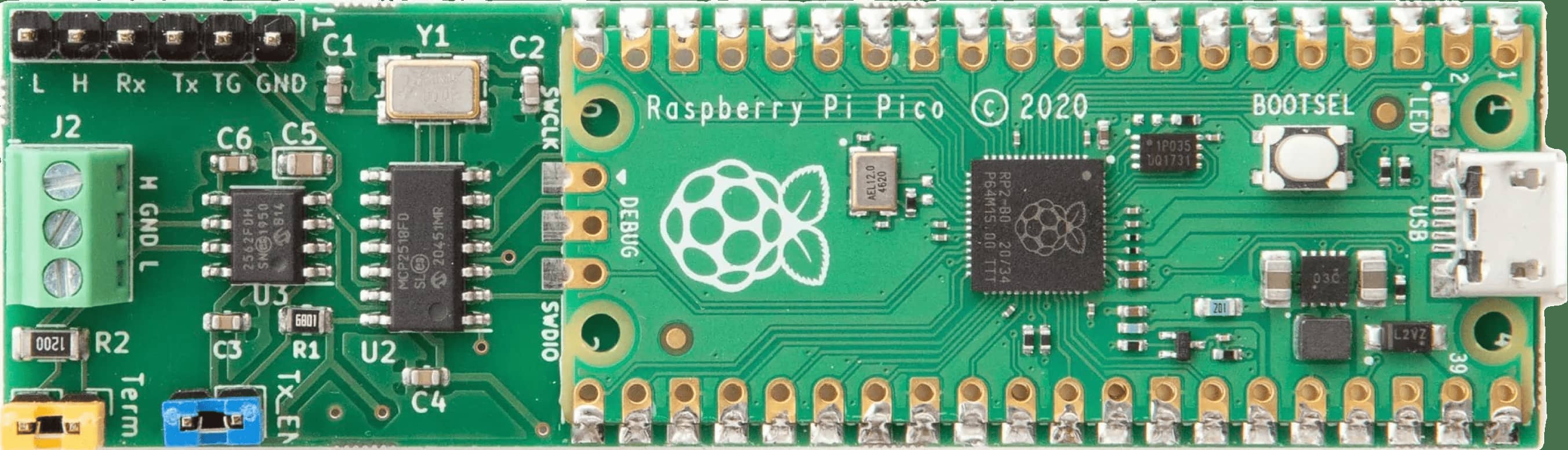
The Canis Labs CANPico is a carrier board for a Raspberry Pi Pico that provides an advanced CAN controller (MCP2517FD) and CAN transceiver, ready for connection to CAN bus wires via a simple screw terminal. The CANPico includes an instrument header with the analog CAN H and CAN L signals and the digital RX and TX signals for use with an oscilloscope or logic analyzer. Software includes an open source SDK for MicroPython (via a custom MicroPython firmware build) and an open source SDK for C. The MicroPython SDK also includes the CANHack toolkit API for mounting low-level attacks on the CAN protocol.
The CANPico is also supported as a development platform for other Canis Labs products and technologies. It is available to buy from SK Pang.
The Canis Labs CryptoCAN encrypted CAN messaging scheme is available for the CANPico via MicroPython firmware with a Python API.
intro to the canpico
A short introduction to the Canis Labs CANPico CAN hardware for the Raspberry Pi Pico. Demonstrates sending CAN frames with the MicroPython CAN API and a logic analyzer with a CAN protocol decoder.
hardware
main features
- Microchip MCP25xxFD CAN controller (MCP2517FD, MCP2518FD or MCP251863) with 2Kbyte buffer space
- Microchip CAN FD transceiver
- Screw terminal for direct access to CAN High/Low twisted pair wiring and a common ground reference
- Jumper for a standard 120Ω CAN bus termination resistor
- Jumper for enabling and disabling transmit input to the transceiver
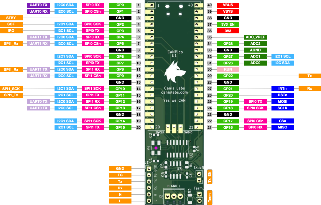
CANPico pin diagram showing CANPico signals in orange (PDF)
interfacing
- SPI interface at up to 18MHz
- Header pins for logic analyzer access to digital CAN signals (TX and RX pins of the transceiver)
- Header pins for oscilloscope access to the analog CAN signals (CAN High/Low, ground)
- TRIG pin for logic analyzer and oscilloscope triggering on programmable CAN events
- Direct GPIO access to CAN RX and TX pins for software error injection
- GPIO control over transceiver low power standby
The other connections are USB (for power and connectivity to a host) and the CAN bus. The 6-pin header is intended for a logic analyzer and oscilloscope to see raw CAN signals, the yellow jumper is for enabling the termination resistor, and the blue jumper enables transmission on the bus (if this is removed then the board is restricted to only listening to the CAN bus, a useful security feature).
reference documentation
CANPico Hardware Reference Manual covers the CANPico hardware and includes schematics (PDF).
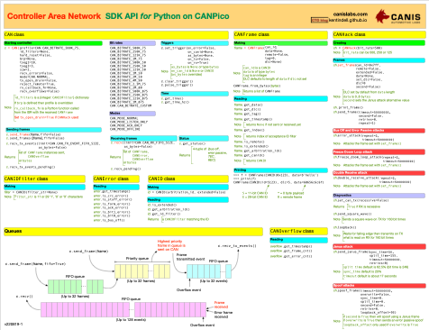
CANPico MicroPython SDK Reference Manual covers the Python API to CAN and CANHack on the CANPico (PDF).

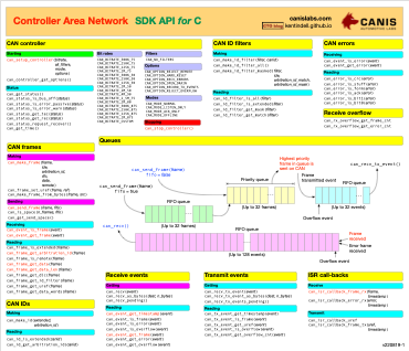
CAN SDK Reference Manual covers the API for C programmers to send and receive CAN frames and manage CAN error and frame transmit events (PDF).
software

The Canis CAN SDK for C GitHub repository contains the source code for the API, CAN drivers and bindings to target microcontrollers, documentation and example code.

The Yes We CAN repository contains source code code for building MicroPython with the CAN and CANHack API for the CANPico (in the CANPico folder).
Pre-built firmware for MicroPython with CAN and CANHack API for CANPico (firmware-20230309-beta.uf2 for the Pico and firmware-20230309-picow-beta.uf2 for the Pico W).
